No products
Prices are tax excluded
Product successfully added to your shopping cart
There are 0 items in your cart. There is 1 item in your cart.


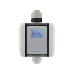
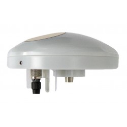
AO-FS1600 Multi-Sensor-Platform - Modbus RTU
New
- Up to 8 measured variables in one device
- Choice of 16 sensors
- Modbus RTU
- high quality case and stainless steel taps
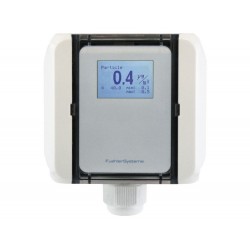
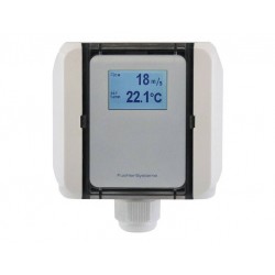
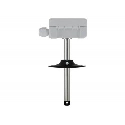
This multi-sensor measuring device can be modularly composed of the following measured variables: temperature, humidity (also heated), air pressure, differential pressure, air quality (CO, CO2, VOC, O2, particle), flow, brightness and motion.
- More info about this product.
- Remove this product from my favorite's list.
- Add this product to my list of favorites.
| Type of Instrument | Multisensor Platform |
| The instrument measures: | Air Quality - VOC |
| The Sensor measures: | Multiple Parameters |
| Output Signal: | Modbus |
This Sensor Platform provides a compact, multi-talent for capturing key environmental conditions in a single instrument with more than 200 configuration options. The digital output is available as Modbus RTU and on-board relay for further signal processing. The high-quality housing series with the new hinge closure technology offers optimal space for the multi-sensor platform. External sensors are safely protected from external influences by aluminum / stainless steel fittings. A 4 inch backlight graphic LCD display visualizes all measured values and also serves to configure the measuring devices using the user menu. The multi-sensor measuring devices are ideal for use in workplaces, production facilities, warehouses, medical facilities or in industry.
For the optional relay output, the switching threshold and hysteresis can be set using a register. Also for the optional display, adjustments such as display content, orientation in 90 ° increments, mode of the backlight, etc. can be specified per register.
As special equipment a potential-free alternating contact and / or a backlit display are available The contents of the display can be rotated in steps of 90 ° by using a command.
As special functions a series of defined measured values from other bus-participants (also cross-manufacturers) can be shown in the display. To display measured values from other bus-participants these are entered into the corresponding register by the bus-Master. The optional alternating contact can be configured for measured values from other bus-participants.
The configuration of address, transmission mode / speed, terminating resistor and master / slave function of the bus-devices can easily be done using the innovative DIP switch technology. Thus devices can quickly and easily integrated into the system and later parameterized via the master.
The bus-devices can even be reset to the works settings during operation of the master. Thus the basic functionality of the device is recreated in a matter of seconds. This can be necessary in the event of incorrect parameterizations of, e.g. offset, switching threshold, display modes etc ...
By means of the FS master / slave topology autarkic nodes without additional SPS master can be installed within the device series. Hereby a bus-device assumes the master function in the node. This requests the measured values from other bus-participants, automatically enters these into the corresponding register and shows them in the internal display. Furthermore the master can evaluate and operate additional actuators in the device series (analogue in- and outputs, relay station).
CO2 air quality sensor
Measurement range CO2 0 ...10.000ppm, optional 20.000ppm or 50.000ppm
Accuracy 0-2000 ppm: ±50 ppm + 2% v. MW, 0-5000 ppm: ±50 ppm + 3% v. MV, else: ±100 ppm + 5% v. MV (at 20°C, 1013
mbar, auto calibration ON)
Temperature dependency CO2: ±5 ppm / K
Pressure dependency compensated if option "air pressure sensor" is selected, else 1.6% of the meassurement value / kp difference to
1013mbar
Response time (t90) < 1 min
Long term stability ±1% FS/year
Sensor Nondispersive infrared sensor (NDIR)
Automatic calibration The automatic drift compensation takes place in the interval of 7 days. This ensures an excellent long-term stability.
The device must be supplied with fresh air within this interval (during continuous operation) for at least 10 minutes.
This function can be deactivated on the device via DIP switch (necessary, if at several consecutive intervals no fresh
air will be supplied).
Manual calibration Manual adjustment to 400 ppm can be executed via registry-command.
Air quality sensor for mixed gas
(VOC)
Measurement range VOC 0-100% (good / bad air quality, referring to the calibration gas)
Accuracy ± 10% FS (at 20°C, 50% r.H. and auto-calibration ON)
Temperature dependency ±0,2% FS/K
Response time (t90) < 1 min
Long term stability ±5% FS/year (auto-calibration ON)
Sensor metal oxide VOC-sensor
Automatic calibration The automatic drift compensation takes place in the interval of 7 days. This ensures an excellent long-term stability.
The device must be supplied with fresh air within this interval (during continuous operation) for at least 10 minutes.
This function can be deactivated on the device via DIP switch.
Manual calibration Manual zeropoint can be setted via registry-command to 10%
Sensitivity Sensitivity can be varied at three levels via registry-command to 10%
CO air quality sensor
Measurement range CO 0-1.000 ppm
Accuracy ±5 ppm + max. ±5% f. mv (at 20°C, 50% r.H.)
Temperature dependency CO: ±5 ppm / K
Response time (t90) < 5 min
Long term stability ±1% FS/year
Sensor Electrochemical gas sensor
Humidity / temperature transducer
Measurement range r.H. 0-100% r.H.
Accuracy humidity ±3% r.H. (30-70% r.H., else ±5% r.H., at 20°C)
Measurement range temperature -20°C...50°C
Accuracy temperature ±0,5 K
Calculated thermodynamic values dew point temperature, abs. humidity, air fuel ratio, enthalpy, wet bulb temperature, vapour pressure
Long term stability ±1% FS/year
Sensors Combined humidity and temperature sensor
Sensor protection high-humidity
range
condensation protection by heating function at more than 95% r.H. ( holding function of the meassured values
during heating function).
Flow rate < 2 m/s
Permanent heated Humidity / temperature transducer
Measurement range r.H. 0-100% r.H.
Accuracy humidity ±3% r.F. (30-70% r.F., sonst ±5% r.F., bei 20°C)
Measurement range temperature -20°C...50°C
Accuracy temperature ±0,5 K
Calculated thermodynamic values dew point temperature, abs. humidity, air fuel ratio, enthalpy, wet bulb temperature, vapour pressure
Long term stability ±1% FS/year
Sensors Combined humidity and temperature sensor + Pt100
Sensor protection high-humidity
range
condensation protection by permanent heating around 3k above ambient temperature
Flow rate < 2 m/s
Air Pressure Sensor
Measurement range atmospheric /
barometric pressure
500-1150 mbar
Accuracy ±3 mbar (at 20°C)
Temperature dependency 1 mbar / 10 K
Linearity inaccuracy ±1% FS
Offset can be set at the registry
Output attentuation can be set at the registry
Pressure Sensor
Measurement range pressure V1: -100...+100 Pa
V2: -500...+500 Pa
V3: -5000...+5000 Pa
Manual zero-point adjustment can be executed
Calculation air flow V1: 0-4.000 m³/h of the differential pressure uo to 100Pa, formula and parameters via registry
V2: 0-20.000 m³/h of the differential pressure uo to 500Pa, formula and parameters via registry
V3: 0-200.000 m³/h of the differential pressure uo to 5000Pa, formula and parameters via registry
Accuracy Difference pressure: ±3,0% FS (at 20°C)
Temperature dependency Difference pressure: ±2,5% FS / 10 k
Linearity inaccuracy Difference pressure / Air Pressure: ±1,0% FS
Offset can be set at the registry
Output attentuation can be set at the registry
Pressure resistance 5-times of measurement range
Manual zero-point adjustment Manual zero-point adjustment can be executed
Motion Sensor
Measurement range motion motion yes/no, apex angle 90°/110° on 360° range, reach 10 m
Response time (t90) < 1 s
Sensor infrared motion sensor MTS 10/360, photodiode
Flow transducer (with pendulum sensor, mounting flange within scope of delivery)
Measuring principle calorimetric measuring method
Measurement range flow V1: 0-5 m/s
V2: 0-20 m/s
Calculation air flow V1: 0-50.000 m³/h, formula and parameters via registry
V2: 0-200.000 m³/h, formula and parameters via registry
Accuracy ±0,3 m/s + max. ±4% FS (@ 20°C, 45% r.H., 1013 mbar)
Temperature dependency ±1% FS/ 10 K
Long term stability ±1% FS/year
Response time (t90) <1s
operating range V1: 0,3-5 m/s
V2: 0,3-20 m/s
Particulate Matter Sensor
Measurement range particulate
matter
0 μg/m³ ... 1000 μg/m³
Accuracy ±5 μg/m³ + max. ±4% FS (@ 20°C, 45% r.H., 1013 mbar)
Temperature dependency ±1% FS / 10 K
Long term stability ±1% FS/year
Response time (t90) <1s
Oxygen sensor
Measurement range oxygen 0…25% vol. optional 0…100% vol.
Accuracy ±5 μg/m³ + max. ±4% FS (@ 20°C, 45% r.H., 1013 mbar)
Temperature dependency ±1% FS / 10 K
Long term stability ±0,2% FS/year at auto calibration ON
Response time (t90) <1s
General:
Supply voltage 24V DC +/-5%
Current consumption typically 100 mA, (depending on MODBUS parameters and selected backlight) plus around 20ma/sensor
Digital output Modbus RTU
Electrical connection push-in terminal, no tools required, time-saving
Display programmable display at 3 levels, customer-specific interfaces optional
Housing Polycarbonate PC UL 94 V0 with hinge locks, color light grey
Cable gland Cable connection 12mm with stain relief
Dimensions Housing: L 150 x W 80 x H 62 mm, without attachements
Protection type Housing/electronic: IP65 (IP20 at option particulate matter and/or CO2), sensor attachments: IP30
Protection class III
Sensor protection (1) r. / Temp, VOC, CO2: in V2A attachments with V2A sintered filter screwed / changeable (2) pressure, differential
pressure, CO, movement: in the housing (3) flow velocity: in V2A pendulum (4) O2, fine dust: internal filter
Working- and Storage temperature -20...+50°C
Range of application Ambient air monitoring, pollution-free, non-condensing air up to max. 98% r.H. (except harmful gases in accordance
with sensor specifications)
Attachments at the device V2A tubes and/or V2A sinter filter
Option clamping connectors / screw
connectors
Steel M12 industrial standard
special features When calculating different sizes, depending on the selected sensor configuration, air pressure, air density, etc. are
included. If these values are not available internally from sensors, they can be entered by the Modbus master into
the corresponding registers of this measuring device. These values are therefore used for the calculation instead of
default values. Further information can be found in the current MODBUS system description.
.jpg)
30 other products in the same category:
-
CX703...
449,00 €
-
MX2204 HOBO...
165,00 €
-
H22-001-C...
550,00 €
-
ULM-500...
-
H22-001-S...
430,00 €
-

RX3004-GSM/...
1 275,00 €
-
RTR-505-Pt...
-
MCR-4TC...
310,00 €
-
MX100...
59,00 €
-
MX2203 HOBO...
155,00 €
-
TR-55i-V...
190,00 €
-
RTR-505-P...
199,00 €
-
RTR-322...
-

DS1922E...
215,00 €
-
DS1922L...
89,00 €
-
DS1922T...
149,00 €
-
DS1921G...
52,00 €
-

DS1922T...
215,00 €
-
DS1922E+DS9...
276,00 €
-
DS1921H-F5...
43,00 €
-
DS1921Z...
58,00 €
-
DS1923-F5...
195,00 €
-
DS1921K...
105,00 €
-
DS1904L-F5...
14,00 €
-
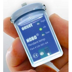
UA-001-64...
85,00 €
-
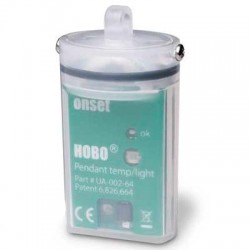
UA-002-64...
105,00 €
-
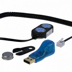
Data Logger...
130,00 €
-
DS1996L-F5...
-
Tempmate-M1...
48,00 €
-
Tempmate.®-...
25,00 €