No products
Prices are tax excluded
Product successfully added to your shopping cart
There are 0 items in your cart. There is 1 item in your cart.


")
")
")

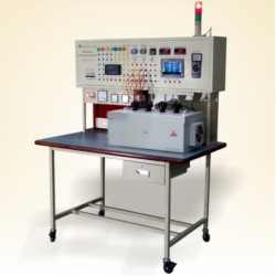
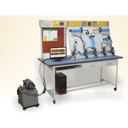
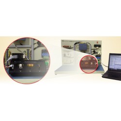
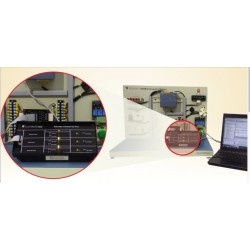
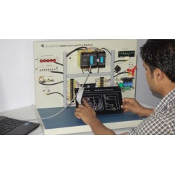
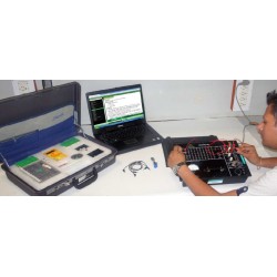
Nvis 9008/ Nvis 9008A Advanced Microwave Integrated Circuit Lab
Nvis9008/Nvis9008A
New
This Training System Includes:
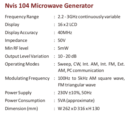
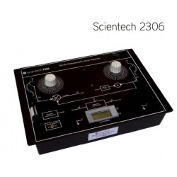
1. Nvis104 Microwave Generator (2.2 - 3 GHz)
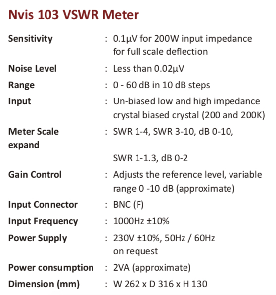
2. Nvis103 VSWR Meter
3. MIC Components
4. Learning Material CD
5. Transmitting and Receiving mast
- Consulta este producto
- Remove this product from my favorite's list.
- Add this product to my list of favorites.
| Category | Training Laboratory |
| Function | Microvawe |
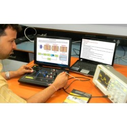
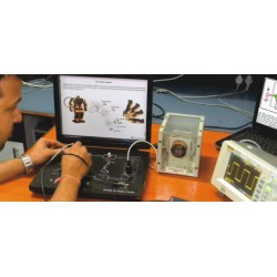
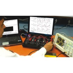
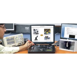
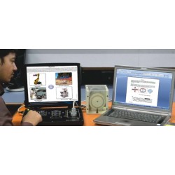
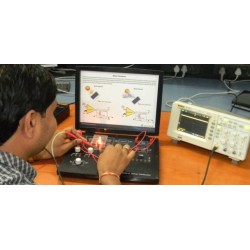
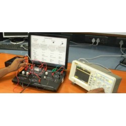
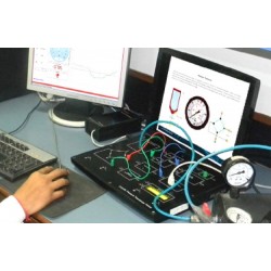
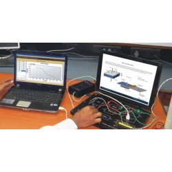
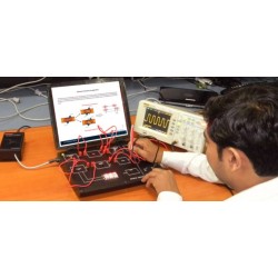
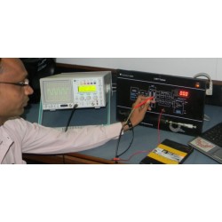
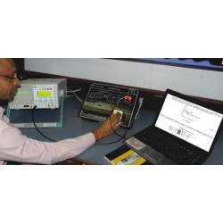
Advanced Microwave Integrated Circuit Lab includes instruments and accessories for studying the characteristics of any MIC ( Integrated Circuits) component over the Frequency Range 2.2 to 3GHz. Characteristics and measurements like Transmission Loss and Reflection Loss of different MIC components can be studied with the help of instruments provided with Nvis 9008/Nvis 9008A. Directivity and Gain of Antennas can also be measured with the setup provided. The theoretical background on these components and experimental details are provided in the learning material CD.
Nvis 9008/ Nvis 9008A, Advanced Microwave Integrated Circuit Lab is an ideal platform to enhance education, training, skills & development amongs our young minds.
- Features:
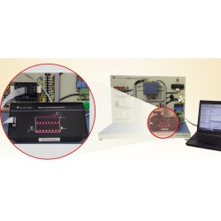
- Complete setup with Generator, MIC Components and Meter
- Gold Plated Components and Connectors
- Microwave Generator with internal AM and FM
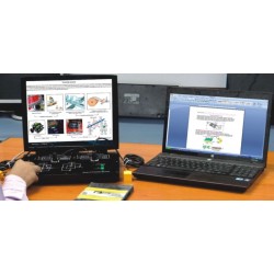
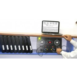
- PC to PC Data Communication
- Antenna Radiation Pattern measurement
- Directivity and Gain measurement
- Learning material CD
+ Specification of MIC Components:
1) Test Jig:
- Includes Of The Following:
a) 10 dB directional coupler
b) Detector
c) Shorts
d) Matched Loads
e) Attenuator
2) Low pass Filter:
- Cut off frequency: 2.5 GHz (approximate)
- Dielectric material: Ceramic Substrate
- Dielectric constant: 3.02
3) Band Pass Filter:
- Center frequency around: 2.4 GHz
- Dielectric material: Ceramic Substrate
- Dielectric constant: 3.02
4) Band Stop Filter:
- Center frequency around: 2.4 GHz
- Dielectric material: Ceramic Substrate
- Dielectric constant: 3.02
5) Branch Line Coupler:
- Dielectric material: Ceramic Substrate
- Dielectric constant: 3.02
- Coupling: 3 dB
6) Rat-Race Coupler:
- Dielectric material: Ceramic Substrate
- Dielectric constant: 3.02
- Coupling: 3 dB
7) Parallel Line Directional Coupler:
- Dielectric Material: Ceramic Substrate
- Dielectric Constant: 3.02
- Coupling: 15dB
8) Power Divider:
- Dielectric Material: Ceramic Substrate
- Output Power: 3 dB
- Return Loss: 8 dB
- Dielectric Constant: 3.02
9) Ring Resonator:
- The Resonance freq: 2.4 GHz
- Dielectric material: Ceramic Substrate
- Dielectric constant: 3.02
10) 50E Microstrip Line:
- Dielectric material: Ceramic Substrate
- Dielectric constant: 3.02
11) RF Switch (Pin Modulator):
- Frequency Range: DC to 5 GHz
- Rise / fall time: 6 ns typical
- Type: SPDT
12) RF Mixer:
- Frequency Range: 2.0 to 7.0 GHz
- Conversion Loss: 6.2 dB typical
- L-R Isolation: 30 dB typical
- RF Power: 50 mW
13) Local Oscillator:
- Frequency Range: 2.2 to 3 GHz
- Tuning Voltage: 5V DC
- Operating Voltage: 5V DC
14) Measuring line:
- Dielectric Material: Ceramic Substrate
- Dielectric Constant: 3.02
15) Isolator:
- Isolation: 15 dB
- Impedance: 50 Ohms
- Insertion loss: 0.8 dB Max
- Avg Power: 5 W
- Design Tolerance: ±5 %
16) Circulator:
- Isolation: 15 dB
- Impedance: 50 Ohms
- Insertion loss: 0.8dB Max
- Avg Power: 5W
- Port: 3
- Design Tolerance: ±5 %
Scope of Learning
- PC to PC Data Communication using MIC components
- Measurement of Transmission Loss and Reflection Loss
- Measurement of substrate dielectric constant using Ring Resonator
- Measurement of power division, isolation and return loss characteristics
- Measurement of coupling, isolation and return loss characteristics
- Measurement of coupling and directivity
- Measurement of Low Pass Filter characteristics
- Measurement of Band Pass Filter characteristics
- Measurement of Band Stop Filter characteristics
- Measurement of characteristics of Patch Antennas
- Measurement of characteristics of an MIC Amplifier
- To study RF switch
- To study RF Mixer
- Measurement of Guide wavelength, Free Space Wavelength and SWR using Measuring Line
- Measurement of Directivity and Gain of Antennas : Yagi Antenna, Patch Antenna, Dipole Antenna
- To study the characteristics of Isolator
- To study the characteristics of Circulator
- Matched Loads (5 Nos.)
- Short
- Coaxial Detector
- Microstrip Directional Coupler (10 dB)
- SMA to SMA Adapters (Both male & female)
- SMA (male) connector fitted cables
- Attenuator (3 dB)
- +12V DC Adaptor
- Transmitting and Receiving Mast
- SMA (Male) to BNC (Female) adaptor
- 3-pin Lunar cable
3MHz - 3GHz Full S-Parameter Vector Network Analyser (Optional):
.jpg)
Features:
- 3MHz–3GHz range
- 100Hz resolution
- 80dB dynamic range
- Full s-parameter test set
- De-embedding capability
- Time domain facility
- P1dBand AM-PM measurements
- Light weight and small footprint
- Low cost
- Exhaustive learning material
30 other products in the same category:
-
Scientech24...
-
Scientech24...
-
Scientech24...
-
Scientech23...
-
ScientechIT...
-
Scientech24...
-
Scientech24...
-
Scientech24...
-
Scientech24...
-
Scientech24...
-
Scientech24...
-
Scientech23...
-
Scientech23...
-
Scientech23...
-
Scientech23...
-
Scientech23...
-
Scientech23...
-
Scientech23...
-
Scientech23...
-
Scientech23...
-
Scientech24...
-
Scientech24...
-
Scientech24...
-
Scientech24...
-
Scientech24...
-
Scientech24...
-
Scientech24...
-
Scientech24...
-
Scientech24...
-
Nvis 6000...
550,00 €