No products
Prices are tax excluded
Product successfully added to your shopping cart
There are 0 items in your cart. There is 1 item in your cart.
 View larger


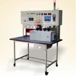
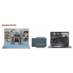
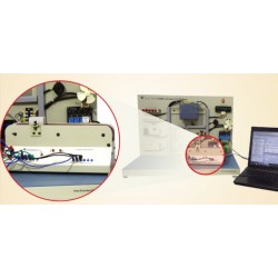
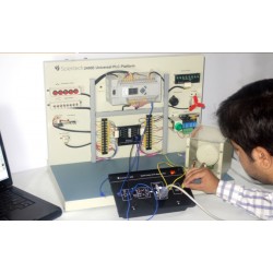
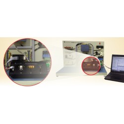
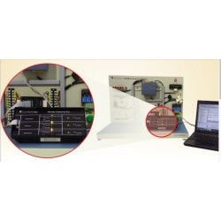
KR-115B Refrigeration Cycle and Heat Pump System with HMI
KR-115B
New
► All system components including condenser, compressor, evaporator, capillary tube, filter, refrigerant receiver, accumulator, manual valves, pressure gauges and expansion devices are front panel mounted for direct operation and observation.
► Three types of expansion devices.
► Provides 6 sight glasses to observe the condition of the coolant.
► High and low pressure protection switches.
► The refrigerant path for the high pressure pipe is painted in red and the low pressure pipe in blue.
► Touch panel displays data
► Use of VNC for wireless control.
- Consulta este producto
- Remove this product from my favorite's list.
- Add this product to my list of favorites.
| Category | Automobile-Automotive |
| Function | Air Conditioning |
Refrigeration Cycle and Heat Pump System HMI KR-115B is designed to learn the theory of Heat Transfer in refrigeration engineering.
► With the proper setup, KR-115B can be emulated as a Refrigeration
or Heat Pump system.
► All system components are mounted on the front panel so students can directly observe, touch the components, and hear the noises produced by the components while they are running under either
Refrigeration or Heat Pump cycle.
► KR-115 offers three expansion devices available for the refrigerant to pass through; they are pressure expansion valve, capillary tube, and
thermal expansion valve.
► Students can use the control panel to switch the preferred expanding path from three expansion devices and compare the corresponding performance under Refrigeration or Heat Pump cycle.
► The status of the refrigerant can be clearly observed through 6 sight glasses at different phases of the Refrigeration / Heat Pump cycle.
► Students can use the valves to lead the refrigerant to the appropriate flowing direction so that the system can operate in corresponding cooling / heating condition.
► If the students mislead the refrigerant to a wrong flowing direction, the pressure protection switches will detect the conflict and halt the compressor to prevent the system from being damaged.
► Using HMI control system, the touch panel can be easily used to control and check the system's experiment status for students. The panel will display system selected working status, temperature and pressure numbers unit easily and change them.
► All system components, including condenser, compressor, evaporator, capillary tube, filter, refrigerant receiver, accumulator, hand valves, pressure gauges, expansion devices, are mounted on the front panel for direct operation and observation.
► Three types of expansion devices, including capillary tube, pressure expansion valve, and thermal expansion valve for refrigerant to pass through.
► Provides 6 sight glasses to observe the refrigerant status before and after passing evaporator, condenser, expansion devices, and compressor.
► Provide high and low pressure protection switches to automatically halt the compressor when detecting wrong refrigerant flowing path.
► The refrigerant path for high pressure tube is painted in red and low pressure tube in blue.
► Use touch panel control and display data
► Can use the VNC for wireless control. (needs use the WIFI AP)
1. Compressor: 1 HP 220VAC, 50Hz/60Hz
2. Refrigerants: R-134a
3. High Pressure Gauge (0~500 psig) and Low Pressure Gauge (0~200 psig)
4. Capillary tube
5. Pressure expansion valve
6. Thermal Expansion Valve (-40 ~+10˚C Pipe Cap. 1.5m)
7. 4-way valve 220V AC max. 2.5Mpa min 0.25Mpa Discharge 3/8" Suction and Coils 5/16"
8. High pressure switch 110psig~430psig with manual reset
9. Low pressure switch 0~80 psig with manual reset
10. Coolant Receiver
11. Cooling accumulator
12. 6 peepholes
13. 9 Solenoid valves
14. Forced fan: 220VAC, 50Hz/60Hz
15. Dimension: (1600 (width) x 580 (depth) x 1890 (height)) mm ± 10%
16. Condenser and evaporator fins are installed with protective net, 15 holes/in2 mesh or more
17. Copper tubes are painted to prevent rust and corrosion.
18. It adopted 40*40mm aluminum extruded bracket and equipped with 4 brake wheels.
19. The panel and the desk are made of iron plates with coating Experiments
20. Under the positive cycle, the initial low pressure of three types of expansion valves should be between 25 and 35 psig
21. The operation and teaching manual is supplied.
22. The manual includes:
a. Detailed experiment procedures for all experiments.
b. Learning objectives of each experiment
c. System principle and characteristics
d. Component operating principle
23. Operating Instruction Slides, containing:
a. Introduction to the structure of the KR-115 and its function
b. Explanation of the cooling circulation system.
c. Component Description
d. Operating procedures
1. Refrigeration circulation system with capillary tube
2. Refrigeration circulation system with pressure expansion control valve
3. Refrigeration circulation system with thermal expansion control valve
4. Reverse cycle heat pump system
5. Reverse cycle heat pump system without refrigerant receiver
6. Drawing Mollier Chart
7. Calculating system performance
8. Comparison of system performance
9. Comparison of energy between cooling and heating experiments
10. Coefficient of performance (COP) and energy efficiency ratio (EER)
.jpg)
30 other products in the same category:
-
Scientech24...
-
Scientech24...
-
Scientech24...
-
Scientech23...
-
ScientechIT...
-
Scientech24...
-
Scientech24...
-
Scientech24...
-
Scientech24...
-
Scientech24...
-
Scientech24...
-
Scientech23...
-
Scientech23...
-
Scientech23...
-
Scientech23...
-
Scientech23...
-
Scientech23...
-
Scientech23...
-
Scientech23...
-
Scientech23...
-
Scientech24...
-
Scientech24...
-
Scientech24...
-
Scientech24...
-
Scientech24...
-
Scientech24...
-
Scientech24...
-
Scientech24...
-
Scientech24...
-
Nvis 6000...
550,00 €