No products
Prices are tax excluded
Product successfully added to your shopping cart
There are 0 items in your cart. There is 1 item in your cart.


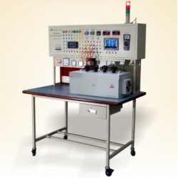
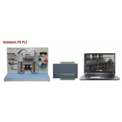
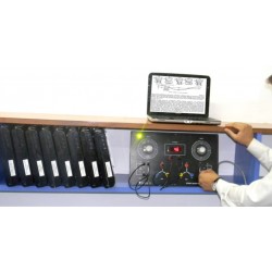
KL-800A CAN BUS Autotronic Training System
KL-800A
New
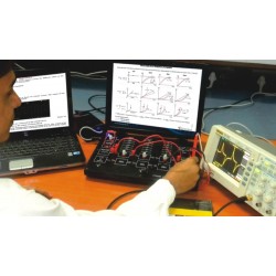
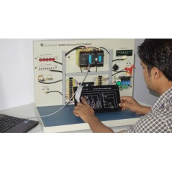
The KL-800A system can simulate the operation of fuel injection system, ignition system and exhaust gas control. Experiments include the characteristics and operation of various sensors and actuators used in automobiles.
- Consulta este producto
- Remove this product from my favorite's list.
- Add this product to my list of favorites.
| Category | Automobile-Automotive |
| Function | CAN BUS Training simulator |
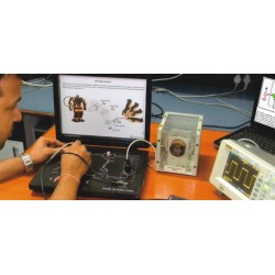
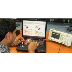
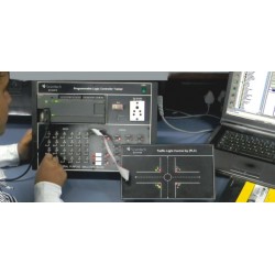
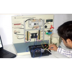
1. CAN-compliant modules can be easily connected together using the 9-pin D-sub connectors and cables. These modules can interoperate with each other.
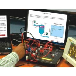
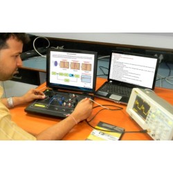
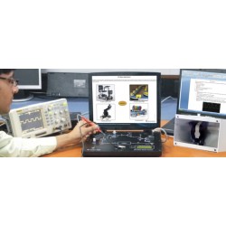
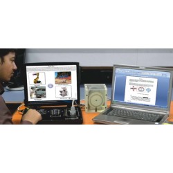
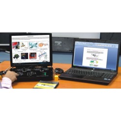
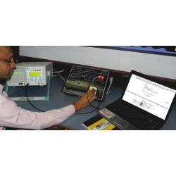
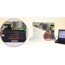
2. User-friendly GUI design allows the user to display and control modules on PC screen.
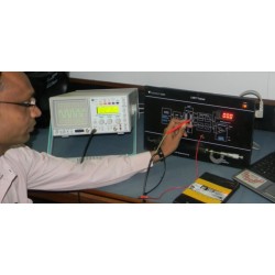
3. Each module is equipped with fault simulation switches for troubleshooting practice.
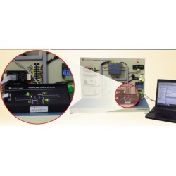
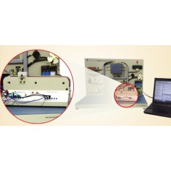
The KL-800A CAN BUS Autotronic Training System is a distributed control system supported by advanced serial bus system CAN (Controller Area Network). CAN is a multi-master bus with an open, linear structure with one bus line and equal nodes. The number of nodes is not limited by the protocol.
Each module of KL-800A system is an ECU or the interoperable device (node) on CAN BUS. Data transfer between modules is achieved by the microcontrollers over CAN BUS. When signals and data are sent to a personal computer, the computer monitoring system displays the current status and data of module on PC screen and turns on the warning light if something is wrong.
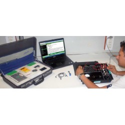
A laptop (not included with the KL-800A) is required for KL-800A operation.
1. Power Supply
(1) DC voltage : +12V
(2) Maximum current : 5A
2. System Requirement
(1) IBM PC or compatible (option)
(2) NI CAN BUS USB interface card
3. Experimental Modules
(1) Equipped with 2mm terminals for testing and checking
(2) Circuit symbols and block diagrams printed on the surface
of module
(3) Module secured in plastic housing; module dimensions:
297 x 226 x 60 mm ±10%
(4) Modules put in the experimental frame for demonstration and experiment
(5) Equipped with fault simulation switches
1. Crankshaft Position Sensor (KL-84001)
(1) Pick-up coil sensor, sensor photo interrupter, sensor hall-effect IC
(2) Output : NE, PHO, HALL
(3) With CAN BUS control interface
2. Air-Flow Sensor (Vane Type) (KL-84002)
(1) VAF output : 0.5V ~ 4.5V
(2) MAT output : 0.3V ~ 4.5V (110°C ~ -5°C)
(3) F/C switch : Controlled by the RPM adjustable knob
(4) With CAN BUS control interface
3. Air-Flow Sensor Hot Wire & Manifold Absolute Pressure Sensor (KL-84003)
(1) Air flow sensor (hot wire type) MAF output voltage : 0.5V ~ 4.5V
(2) Manifold absolute pressure sensor MAP output voltage : 1.2V ~ 3.6V (-80kpa ~ 0kpa)
(3) With CAN BUS control interface
4. TPS & CTS & O Sensor 2 (KL-84004)
(1) Throttle position sensor (TPS) TPS output voltage : 0.5V ~ 4.5V
(2) Coolant temperature sensor (CTS)
a. CTS output voltage : 0.3V ~ 4.5V
b. CTS voltage / temperature : 4.3V/-5°C, 3.7V/10°C, 3V/25°C, 2.2V/40°C, 1.2V/65°C, 0.3V/110°C
(3) Oxygen sensor
a. O output voltage 2
· Normal : 0.1 ~ 1.0V
· Rich : 0.6 ~ 1.0V
· Lean : 0.1 ~ 0.3V
b. Selector switch for selecting normal, rich and lean
(4) With CAN BUS control interface
5. P/N, A/C, PSPS, 3GR Switch & Vehicle Speed Sensor (KL-84005)
(1) P/N switch : Park / Neutral switch
(2) A/C switch : Air Conditioning switch
(3) PSPS switch : Power Steering Pressure Switch
(4) Vehicle speed sensor Speed adjustable : 0 ~ 120km/hr
(5) 3GR switch
(6) With CAN BUS control interface
6. Fuel Injectors / Spark Plugs (KL-84006)
(1) Fuel injector control
a. Coil resistance of injector : 18
b. Maximum engine speed : 3600rpm
c. Selectable injection modes : Synchronous, Non-synchronous, sequential
d. Injection sequence displayed by LEDs
(2) With CAN BUS control interface
7. Ignition system (KL-84007)
(1) Single-output of ignition coil
a. Coil resistance : 2Ω
b. Computer-controlled ignition displayed by LEDs
(2) Double-output of ignition coil
a. Coil resistance : 1Ω
b. Computer-controlled ignition displayed by LEDs
(3) With CAN BUS control interface
8. Cooling Fan & Fuel Pump & A/C Compressor Relays (KL-84008)
(1) Cooling fan
a. Control signal : FANC
b. 12V DC motor driven
c. Actuating conditions : A/C switch ON or coolant temperature sensor (CTS) signal higher than 108°C
(2) Fuel pump
a. Control signal : F/C
b. 12V DC motor driven
c. Actuating conditions : F/C switch of vane air flow sensor ON and engine running (RPM signal)
(3) A/C compressor
a. Control signal : ACC
b. 12V DC motor driven
c. Actuating condition : A/C switch ON
(4) With CAN BUS control interface
9. Idle Air Control Valve (KL-84009)
(1) Step motor driven
(2) Control signals : IAC1, IAC2, IAC3, IAC4
(3) Actuating conditions : P/N or A/C or PSPS switch ON/OFF
(4) With CAN BUS control interface
10. TCC & CCP & EGRV (KL-84010)
(1) Torque converter clutch
a. Control signal : TCC
b. 12VDC solenoid valve
c. Actuating conditions: vehicle speed sensor (VSS) signal higher than 40km/hr and 3GR switch ON (2) Carbon canister purge valve
a. Control signal : CCP
b. 12VDC carbon canister purge valve
c. Actuating conditions
· RPM signal : engine speed faster than 1200 rpm
· CTS signal : coolant temperature greater than 65°C
· TPS output voltage : 1.0 ~ 2.5V
(3) Exhaust gas recirculation valve
a. Control signal : EGRV
b. 12VDC exhaust gas recirculation valve
c. Actuating conditions :
· RPM signal : engine speed faster than 1200 rpm
· CTS signal : coolant temperature greater than 65°C
· TPS output voltage : 1.0 ~ 2.5V
· MAP output voltage : 1.6 ~ 1.8V
(4) With CAN BUS control interface
Experiment 1 Engine Speed Sensors
Experiment 2 Air-Flow Sensors
Experiment 3 Throttle Position Sensor
Experiment 4 Coolant Temperature Sensor
Experiment 5 Oxygen Sensor
Experiment 6 Vehicle Speed Sensor
Experiment 7 Third Gear Switch
Experiment 8 Park/Neutral Switch
Experiment 9 Air Conditioning Switch
Experiment 10 Power Steering Pressure Switch
Experiment 11 Injector Circuit
Experiment 12 Computer-Controlled Ignition System
Experiment 13 Cooling Fan Relay Circuit
Experiment 14 Fuel Pump Relay Circuit
Experiment 15 A/C Compressor Relay Circuit
Experiment 16 Idle Air Control Valve
Experiment 17 Torque Converter Clutch
Experiment 18 Carbon Canister Purge Valve
Experiment 19 Exhaust Gas Recirculation Valve
Experiment 20 Car Computer
K-800A Accessories (KL-89002)
1. 9-pin D-sub RS-232 cables :
(1) 180cm male-to-female cable : 1 pce
(2) 40cm female-to-female cable : 1 pce
2. NI CAN BUS USB interface card
3. AC adapter : 12VDC / 5A
4. Manual vacuum pump
5. Experiment manual, instructor manual, CD for KL-800A
6. Power cord
7. Rack frame (KL-97002)
8. Connector leads : 2mm-2mm : 1set
9. Storage cabinet : 2 sets
30 other products in the same category:
-
Scientech24...
-
Scientech24...
-
Scientech24...
-
Scientech23...
-
ScientechIT...
-
Scientech24...
-
Scientech24...
-
Scientech24...
-
Scientech24...
-
Scientech24...
-
Scientech24...
-
Scientech23...
-
Scientech23...
-
Scientech23...
-
Scientech23...
-
Scientech23...
-
Scientech23...
-
Scientech23...
-
Scientech23...
-
Scientech23...
-
Scientech24...
-
Scientech24...
-
Scientech24...
-
Scientech24...
-
Scientech24...
-
Scientech24...
-
Scientech24...
-
Scientech24...
-
Scientech24...
-
Nvis 6000...
550,00 €