Shopping Cart


Replace your expensive data logger, and turn your PC into an affordable SDI data logger with the SDI-12 to USB Protocol Translator board.
Plug in the board into a USB port, open Windows HyperTerminal, and you are ready to query SDI-12 compliant sensors.
Features:
► Affordable.
► Fully SDI-12 compliant.
► Sends SDI-12 commands and passes back the responses.
► Powered from the USB interface.
► Low power.
► Can be used with any serial communication program.
► Command line interface.
► Can interface with up to 62 SDI-12 Addresses.
► Automatically sample up to 20 different sensors, using the scheduler.
► Easy to mount with 4 mounting holes in corners.
► Works with: Windows, Linux, and Apple OS.
SDI-12 to USB Translator:
Although SDI-12 is a cryptic 2-wire hardware and software protocol, it is still a widely used standard interface between environmental sensors and data loggers. Up to now, sensor users have had the difficult and costly burden of creating their own SDI-12 solutions from zero. Because of the many eccentricities of the SDI-12 protocol, it is a difficult task to create a truly compliant SDI-12 sensor interface.
The SDI-12 Translator solves the SDI problem, by allowing your to quickly turn your computer into an SDI-12 enabled logger, or terminal, and talk to SDI-12 compliant sensors.
Runs with any Serial Terminal Program:
The translator's USB port emulates a serial port so you can use any serial port communication program such as Putty, Termite, or HyperTerminal to communicate with the device through a command line interface.
You can also write your own software programs to communicate with the translator board, and merely need to target a serial port on your computer. We've created an Online Serial Terminal Application that you can run from any Chrome or Edge browser, that will allow you to communicate with your device.
Transparent Mode or Data Logger Mode:
The translator allows you to pass through raw SDI-12 commands, or you can use the translator as a data logger by setting up the on-board scheduler. As a data logger, it will retrieve data at specified intervals, and save the data to your PC as a CSV file. Note that the terminal software that you select should have file save capability.
Power From USB:
The translator is low-power and can be directly powered from the USB cable.
Other SDI-12 Solutions:
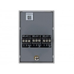
If you have a sensor that doesn't have SDI-12 capability, you can user our SDI-12 Sensor Translator to quickly convert voltage output sensors into SDI-12 compliant sensors. If you're new to SDI-12, and want a simple, easy to learn, evaluation system to speed up your learning SDI-12, we recommend getting both a SDI-12 USB translator, and an SDI-12 Sensor Translator which can talk to each other.
We also have an RS232 to SDI-12 translator Model SDI-12-TRANS-RS232 which may be of interest to you.
![]()
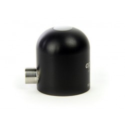
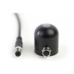
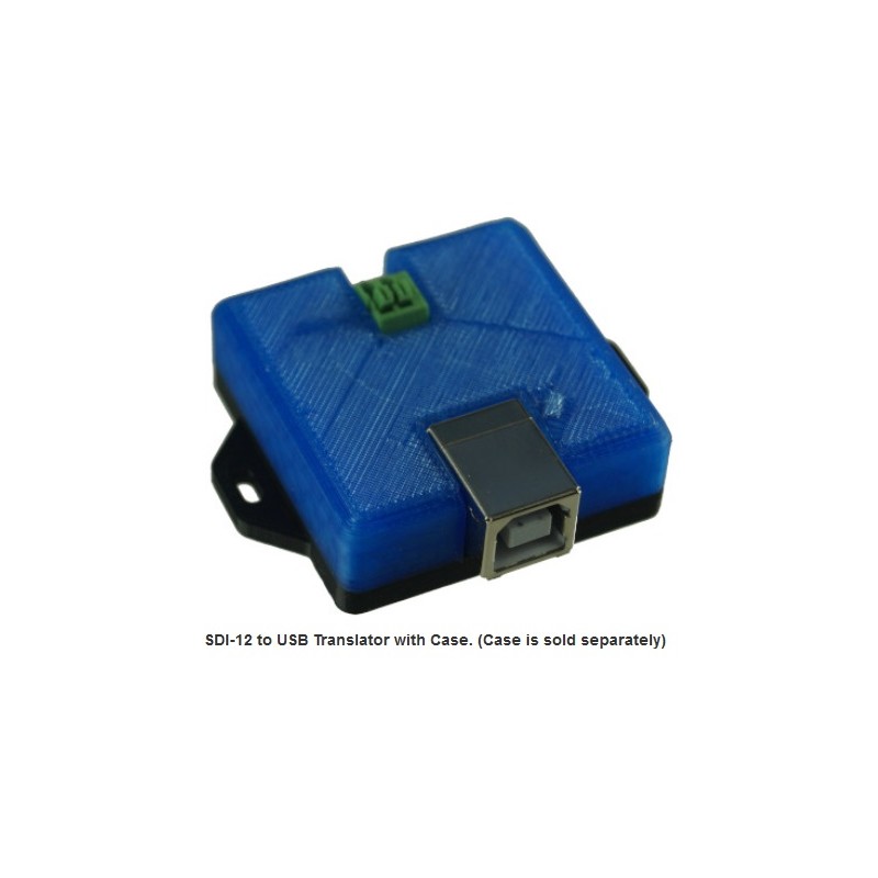
► Easy to Mount Enclosure
To keep the cost low, we sell the board by itself, or you can optionally pair it with an enclosure. The enclosure is made of 3D printed PLA.
The top part is of the case is transparent, enabling you to see the internal LED.
The bottom part has flanges with mounting holes, making it easy to mount.
![]()
Applications:
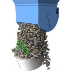
► Crop Steering.
► Ultra-fast prototyping of SDI-12 sensor networks.
► Replacement of expensive data loggers.
► Environmental/Weather monitoring.
► Control and monitoring of irrigation systems.
► SDI-12 testing of sensors.
Software Setup:
A serial communications program must be used to access the translator. While the translator will work with most any serial communications program, we recommend using our Online Serial Terminal Application which will work with Chrome and Edge browsers.
When you plug a USB Comm device into your computer it will randomly assign a comm port number. To determine which comm port the device has been assigned to do the following:
- Open Windows device manager. This can be access through the control panel.
- Plug in the USB device. You should see the device under the tree node labeled: "Ports (COM & LPT)"
- When you un-plug the USB device, that device should disappear. You now know the correct comm port number.
Now that you have the correct comm port number for the device, connect to it with our Online Serial Terminal Application from your browser (Chrome or Edge). Select "SDI-12 Translator" from the product list, press the connect button, and select the correct comm port that you determined from the steps above.
If you're using a different serial port terminal app, then you'll need to configure it with the following options:
- Select the comm port that you determined from the steps above.
- Set the Baud Rate to 115200. (Note if you have Rev 1.00 of the software the baud rate is 9600.)
- Data bits should be 8.
- Stop bits should be 1.
- Parity should be none.
- Flow Control should be none.
- Select "Append CR".
Commands:
You can setup the board to act as a data logger and to sample the various sensors at periodic times, by using the "ADD" command, or you can use the transparent mode, and send the sensors any SDI-12 text string that you desire. "<CR>" as used below means carriage return with no line feed. Some communication software programs have an option to automatically send a line feed with the carriage return. Make sure this feature is disabled.
Command Description
H Help - Lists all of the available commands
ADD [sensor number (0-9)]:[Measurement number], [sample period (in seconds, 0 for no sampling)],[use CRC (1:true/0:false)], [Type (0:Normal,1:Concurrent,2:Continuous)]<CR> Add a sensor/measurement number to the scheduler which periodically goes out and samples the specified sensor and measurement. You can specify sample period, and type, and if you want to use CRC.
Example: ADD 0:0,120,0,0<CR> - sensor 1 is sampled every 2 minutes without CRC.
Up to 20 sensors can be added to the scheduler.
DEL [sensor number (0-9)]:[Measurement number]<CR> Remove a sensor/measurement from the scheduler.
START<CR> Turn on the scheduler and begin sampling for each sensor/measurement added using the ADD command.
STOP<CR> Turn off the scheduler and stop sampling.
QUERY [sensor address (0-9)]:[Measurement number]<CR> Returns the information specified by a particular ADD commands, and SDI ID string.
V<CR> - Returns the version Number of the SDI USB Translator. (Current Version: V2.6)
READ [sensor address (0-9)]:[Measurement number]<CR> Perform immediate measurement.
T [String]<CR> Transparently sends a string to SDI bus.
Responses from Logger
DATA [sensor number (0-9)]:[Measurement number]<SDI values> Response from logger to measurements.
Error Codes:
If your sensor is working correctly you should never see these error codes.
Error Description
ER: (2) response The sensor has returned an unexpected number of parameters 'n' from the sensor response: atttnrn
ER: (3) response The sensor has returned an invalid time 'ttt' from the sensor response: atttnrn
USB Drivers:
The translator works with Windows, Linux, and Apple OS.
Determine your board revision by looking at the silk screen on the board. Most windows systems already have these drivers installed.
Board Revision Driver Link
Rev J or Higher: Proflic USB Driver
Rev A through Rev H: FTDI USB Driver
Quick Start Guide:
Plug the translator into the USB port. You will see its LEDs blink briefly.
Open the Online Serial Terminal Application in a Chrome or Edge browser.
Under "Product" select "SDI-12 Translator", and press connect.
Select the correct Comm port.
Press the "Send Command" button. The translator should respond with an error message.
Wire a single SDI-12 Sensor to the SDI-12 bus of the translator, and make sure your sensor is powered.
Send an address query command in transparent mode by sending the following string from your terminal program:
T ?! // The sensor should respond with its address.
You can send the sensor other SDI-12 commands in transparent mode such as:
T 0M! // Measurement command.
T 0D0! // Get data command.
Make sure each of your sensors have a different address so that there is no conflict on the bus. You can change the sensor address with the change address command. The following example assumes that the sensor is currently at address 0, and you want to change it to address 1:
T 0A1! // The sensor should respond with its new address.
How to Get Started:
The best way to get started is to order a few sample translators and relay boards from our website store and try them out in your application.


