No products
Prices are tax excluded
Product successfully added to your shopping cart
There are 0 items in your cart. There is 1 item in your cart.


CERES Temp. Humidity & CE Soil Sensor (SDI-12 or RS485)
New
Sensor of the soil temperature, soil moisture, the electrical conductivity of the soil, the complex dielectric permittivity of the soil and the electrical conductivity of the "water pores" contained in the soil hole.
Both the conductivity of the soil and the water of the pores are automatically compensated by the temperature.
Includes standard 5 meter cable
- Consulta este producto
- Remove this product from my favorite's list.
- Add this product to my list of favorites.
| The Sensor measures: | EC/DP/Hum./Temp/ECWP |
| Cable Length: | 5 meters |
Ground sensor based on physical measurements and the behavior of an electromagnetic radio wave reflected in the ground. It is based on the measurement of soil impedance through reflectometry in the frequency domain, the probe determines the dielectric permittivity. The complex dielectric permittivity allows the sensor to simultaneously calculate the soil moisture and the electrical conductivity of the soil. The sensor uses a frequency of 50 MHz, which minimizes the effects of texture and salinity, which makes measurements accurate on most hydroponic substrates.
The electrical conductivity of the "pore water" is calculated using algorithms based on soil moisture and values of electrical conductivity in the soil.
Components
This sensor is designed to remain buried for years in the ground.
The probe consists of three main components:
Stainless steel teeth set with marine grade.
Nylon: The outer shell is composed of this material.
Epoxy resin: Provides internal electronic protection as well as a robust construction design.
MEASURED PARAMETERS
Temperature
The user can measure the soil temperature in Celsius or Fahrenheit. The soil temperature varies in a range of -20ºC to + 65ºC.
Humidity
The sensor provides soil moisture measurements in units of water fraction by volume (wfv or m3m-3), that is, a percentage of soil water shown in decimal form. For example, a water content of 0.20 wfv means that a liter of soil sample contains 200ml of water. Precise measurements of soil moisture in a range of 0 to 0.5 wfv. Outside this range the values are not accurate.
Electric Conductivity (EC)
The sensor measures the electrical conductivity in situ in units of millisiemens per centimeter in a range of 0 to 15 mS / cm. The electrical conductivity is compensated with the soil temperature. The range can be extended with specific calibrations.
Electrical Conductivity of the "water pore"
The sensor provides the electrical conductivity measurements of the "water pore" found in soil holes. In this way, the user can obtain the electrical conductivity of the water that is in the root zone after irrigation. This measurement depends on the soil moisture and the electrical conductivity of the soil, according to the algorithm used. The electrical conductivity is compensated with the temperature.
.jpg)
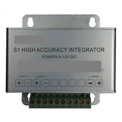
POWER DRAIN: 20mA (Standby) – 100mA (Measuring)
| Network Wire | |
|---|---|
| White-Brown | 12VCC IN |
| Brown | GND |
| White-Green | RS-485 A |
| Green | RS-485 B |
Sensor Communication
The probe is available in a digital RS-485 version. The sensor incorporates a microprocessor to process the information from the probe into useful data. The data is then transmitted digitally to a receiving instrument with RS-485 communication. The RS-485 communication format has two data cables and has a custom communication protocol.
Addressing and programming
The floor sensor can be connected in parallel so that multiple probes can be connected to a single communications port of a data logger or other device. When multiple probes are connected in this manner, each probe must be assigned a unique address. In this way, the user can select which probe to use and select what data will be transmitted. Once the probe is connected and power is applied, a terminal emulation program such as Hyperterminal starts on the PC. Certain settings will need to be configured to enable communications with the probe. The following settings are for Hyper Terminal, but most terminal emulation programs should have equivalent settings.
The following table provides configuration information.
COM Port It must correspond to the real port on the PC where the communication cable is connected. For example: COM1, COM2, etc.
Baud rate 96000
Data bits 8
Parity None
Stop bits 1
Flow control None
Also, these settings will make the program easier to use. In Hyperterminal, these settings are found in File / Properties / Settings / ASCII Settings / ACSII Send:
Check "Send end of line with line feeds". All commands sent to an RS-485 version of the sensor must end with a "Carriage Return" "Line Feed" pair.
Check "I Echo Locally Written Characters". The sensor does not repeat any commands. Checking this allows you to see what you have typed.
The following tables illustrate the format of the commands used:
<addr>CC<CR> <LF>
<addr>
3 byte address (0-999)
CC Command
<CR>
Carriage return character (ASCII 13)
<LF>
Linefeed character (ASCII 10)
<SERIAL>
DDD
3 byte address
XX 2 byte week
Yy
2 byte year
ZZZ 3 byte version
WWWW
4 byte serial number
The following tables illustrate the commands used:
Serial number Direction Change of direction Low consumption Reading take Reading sample *
Description Returns the factory serial number Returns the probe address Changes the probe address
Sensor reduces current consumption in sensors with old software
(before V400). Reduce from 50mA to 20mA in standby.
Take reading samples
Access level Read only Read only Write only Execute Execute Execute
Command
/// SN =? <CR> <LF>
/// AD =? <CR> <LF> <oldAddr>AD=<newAddr><CR> <LF>
<addr>CL<CR> <LF>
<addr>TR<CR> <LF>
<addr>T3<CR> <LF>
Response <SERIAL><CR> <LF> <addr><CR> <LF>
<newAddr><CR> <LF>
<addr>CLOK<CR> <LF>
None <addr> <STC>, <STF>, <M>, <Ltg>, <CP <Wtc>, <Er>, <ErTC>, <Ei>, <EiTC>, <CStc>, <TElec>, <CR> <LF>
Example /// SN =? 00012184000396 /// AD =? 000 000AD = 001
001
000CL
000CLOK
Measure in water:
000TR
000T3
000 + 20.4, + 68.8, + 0.794, + 0.179, + 0.064, + 78.728, + 79.669, + 19.892, + 21.278, + 0.060, + 21.5
Read sample *: The response <addr> <STC>, <STF>, <M>, <Ltg>, <CPWtc>, <Er>, <ErTC>, <Ei>, <EiTC>, <CStc>, <TElec>,<CR> <LF> is detailed below:
<STC>: ground temperature in Celsius
<STF>: ground temperature in Fahrenheit
<M>: Humidity (0 to 1 equals 0 to 100%)
<Ltg>: complex dielectric permittivity loss tangent
<CPWtc>: compensated "pore water" temperature conductivity (S / m)
<Er>: real part of the dielectric permittivity
<ErTC>: real temperature corrected for dielectric permittivity
<Ei>: Imaginary part of the dielectric permittivity
<EiTC>: imaginary temperature corrected for dielectric permittivity
<CStc>: compensated mean conductivity temperature (S / m)
<TElec>: temperature of the internal electronics.
30 other products in the same category:
-
AO-RRF(P)/A...
225,00 €
-

AO-RRF(P)/A...
175,00 €
-

AO-RDF/A...
225,00 €
-
AO-RDF/A...
175,00 €
-
AO-RDFT/A...
255,00 €
-

AO-RDFT/A...
205,00 €
-
AO-RRFT(P)/...
270,00 €
-
AO-DW/H...
36,50 €
-
AO-CO2-U/A...
310,00 €
-
AO-RL2/A...
275,00 €
-
AO-ST-P-DA...
178,00 €
-
AO-WFR/N...
95,00 €
-
AO-SCT27H...
28,00 €
-
AO-SCT10027...
28,00 €
-

AO-SCT10024...
35,00 €
-
AO-SCT10016...
24,00 €
-
AO-CO-M/A...
750,00 €
-
AO-CO2-M/A...
825,00 €
-
AO-DET...
37,00 €
-
Flexible...
-
AO-D1...
65,00 €
-
AO-S10...
30,00 €
-
AO-S9...
70,00 €
-
AO-AD/A...
247,00 €
-
High...
300,00 €
-
AO-SCT010T-...
12,00 €
-
AO-SCT024TS...
-
AO-SCT036TS...
-

AO-TCVD-10...
-
AO-TCVD-500...