Ningún producto
Estos precios se entienden sin IVA
Su producto se agregó correctamente al carro
Hay 0 productos en su carro. Hay 1 producto en su carro.


BeeWave Plataforma modular de educación y creación de prototipos de RF
BeeWave
Nuevo
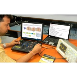
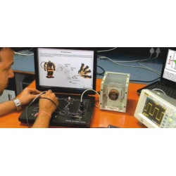
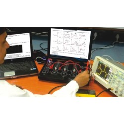
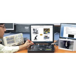
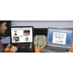
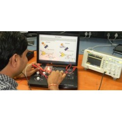
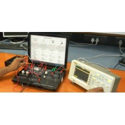
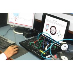
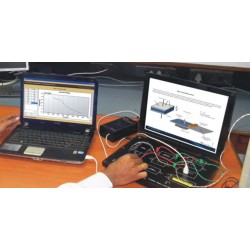
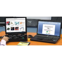
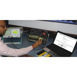
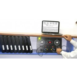
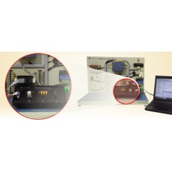
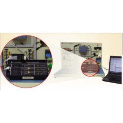
◆ BeeWave es un concepto novedoso que permite a los usuarios construir circuitos de RF completos con sus propias manos, desde la comodidad de sus escritorios y sin necesidad de herramientas especiales.
◆ Ya no tendrá que preocuparse por polarizar, alimentar o hacer coincidir pistas complejas en su PCB, BeeWave actúa como una placa de pruebas de RF donde solo necesita colocar y conectar diferentes módulos (cada uno de los cuales representa una función de RF) y dejar que BeeWave se preocupe por el resto.
- Consulta este producto
- Remove this product from my favorite's list.
- Add this product to my list of favorites.
- Imprimir
| Categoría | Telecomunicaciones |
| Función | Transmisiones |
► La construcción de PCB de RF ha sido una barrera importante a la que se enfrentan los diseñadores y educadores de circuitos de RF y microondas. El diseño complejo, la fabricación costosa y la difícil resolución de problemas obligaron a muchos diseñadores a depender principalmente de cálculos teóricos y simulaciones, lo que condujo a diseños subóptimos y una mala experiencia en el aula.
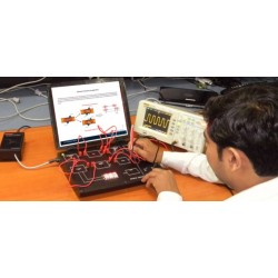
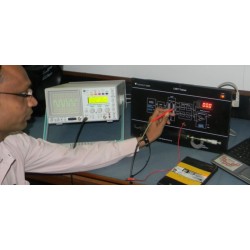
► El rendimiento superior de RF convierte a BeeWave en una herramienta ideal para la creación de prototipos profesionales, mientras que la facilidad de uso, las configuraciones de enseñanza prediseñadas y la conectividad PC/Matlab la convierten en una herramienta perfecta para enseñar conceptos inalámbricos y de RF de forma práctica en lugar de hacerlo en una pantalla de computadora.
Características y beneficios:
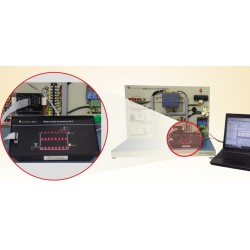
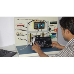
► Módulos Plug & Play listos para usar para funciones típicas de RF de hasta 6 GHz
► Conecte módulos y construya circuitos RF completos en cuestión de minutos
► Ideal para educación práctica sobre conceptos de RF y microondas.
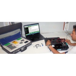
► La forma más rápida de crear prototipos, probar y validar diseños de circuitos de RF
► Construya cualquier circuito de RF y microondas sin la necesidad de un complejo diseño y fabricación de PCB de RF
► Mejore su diseño a través de múltiples iteraciones de diseño sin el costo o el retraso de la refabricación de PCB
► Configuraciones listas para usar para educación y capacitación en el aula
► Módulos controlados por PC, compatibles con Matlab
AMP6000 Fixed gain amplifier optimized for applications requiring high performance & wide bandwidth gain blocks
- Frequency Range: 10 MHz to 6000 MHz
- Gain: 14 dB
- P1dB Output Power: 15 dBm
- Input Return Loss (S11): -20 dB
- Output Return Loss (S22): -9 dB
- Reverse Isolation: 25 dB
- Max. DC Voltage at input or output: 25 V
- Max RF input power: 20 dBm
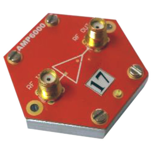
AMP6000
VGA6000 Variable gain amplifier
- Frequency Range: 10 – 6000 MHz
- Gain Setting: -19.75 to 12 dB
- Gain Resolution: 0.25 dB (Typical)
- P1dB Output Power: 15 dBm
- Input Return Loss (S11): -15 dB
- Output Return Loss (S22): -10 dB
- Reverse Isolation: 23 dB
- Max. DC Voltage at input or output: 25 V
- Max. RF input power: 20 dBm
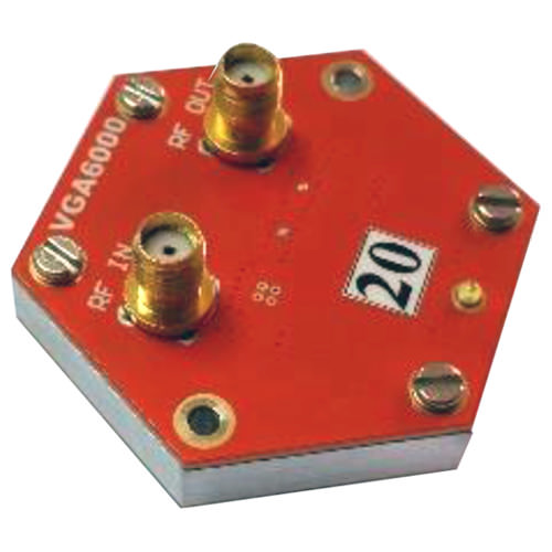
VGA6000
VGA1000 Variable gain amplifier
- Frequency Range: 50 – 1000 MHz
- Gain Setting: -12.25 to 19.5 dB
- Gain Resolution: 0.25 dB (Typical)
- Input Return Loss (S11): -15 dB
- Output Return Loss (S22): -15 dB
- Reverse Isolation: 25 dB
- Max. DC Voltage at input or output: 25 V
- Max. RF input power: 20 dBm
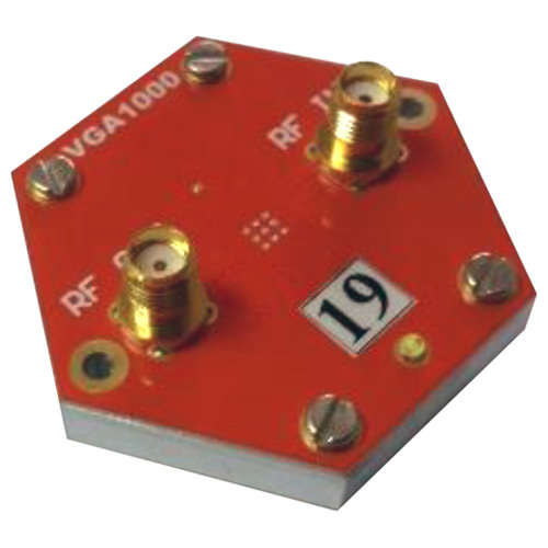
VGA1000
lna2700 Wideband low noise amplifier
- Frequency Range: 700-2700 MHz
- Saturated Output Power: 18 dBm
- 1 dB Output Compression Point: 15 dBm
- Noise Figure: 2dB
- Small Signal Gain (S21): 16 dB
- Input Return Loss (S11): -18 dB
- Output Return Loss (S22): -17 dB
- DC Voltage (RF in , RF out): 25 Vdc
- Max. RF input power: +20 dBm
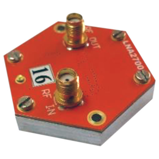
lna2700
BPF_CER1 Band Pass Filter based on ceramic filters technology
- Bandwidth: 100 – 1020 MHz
- Center Frequency: 2450 - 5500 MHz
- Return Loss: -22 dB
- Pass Band Insertion Loss: -5 dB
- Stop Band Attenuation: -40 dB
- Max. RF input power: 20 dBm
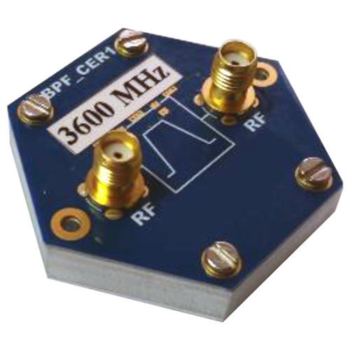
BPF_CER1
BPF_SAW1 Band Pass Filter based on SAW (Surface Acoustic Wave) technology
- Bandwidth: 2 – 80 MHz
- Center Frequency: 315 - 2440 MHz
- Return Loss: -20 dB
- Pass Band Insertion Loss: -2 dB
- Stop Band Attenuation: -40 dB
- Max. RF input power: 20 dBm
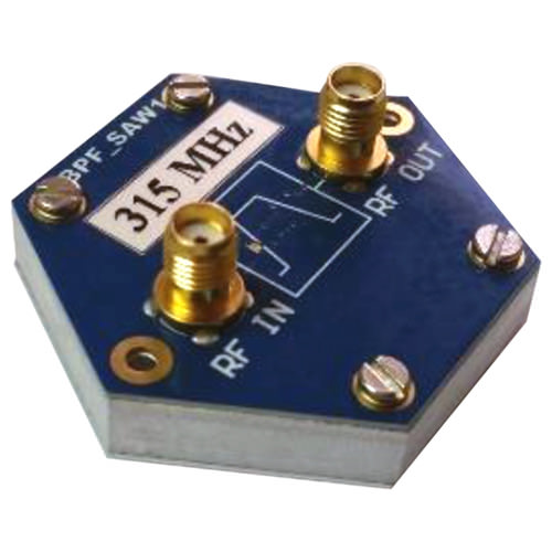
BPF_SAW1
BPF_SAW2 Band Pass Filter
- Bandwidth: 40 – 72 MHz
- Center Frequency: 1900 - 2436 MHz
- Return Loss: --17.5 dB
- Pass Band Insertion Loss: -1 dB
- Stop Band Attenuation: -35 dB
- Max. RF input power: 20dBm
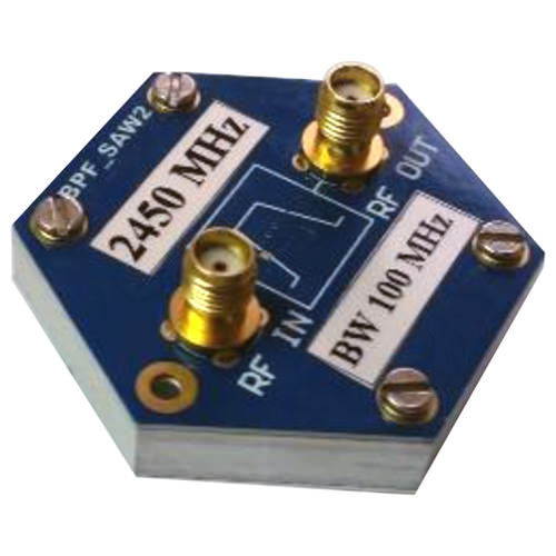
BPF_SAW2
LPF _CER1 Ceramic Low pass filter module
- Cutoff Frequency: 150 – 6000 MHz
- Return Loss: -20 dB
- Pass Band Insertion Loss: -3 dB
- Stop Band Attenuation: -50 dB
- Max. RF input power: 20 dBm
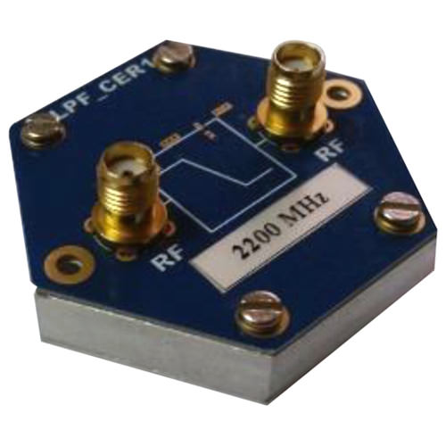
LPF _CER1
MX1 High performance, Wide band Microwave double balanced passive mixer(can be used for frequency up-conversion or downconversion)
- Frequency Range
- RF : 2-14 GHz
- LO : 1-12 GHz
- IF :10 – 6000 MHz
- Return Loss:
- RF : -25 TO -9 dB
- LO : -25 TO -5 dB
- IF : -17 TO -5 dB
- Conversion loss : 8 dB @ 6 GHz
- LO to IF Leakage: -25 dBm
- RF to IF Isolation: 40 dB
- SSB Noise Figure @ 6 GHz: 8 dB
- IIP3 @ 6 GHz: 24 dBm
- Max. DC Voltage at input or output: 25 V
- RF and IF input power: 20 dBm
- LO input power: 10 dBm
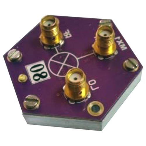
MX1
LO6000 Ultra-wideband phaselocked loop (PLL) with integrated voltage control oscillators (VCOs)with good phase noise and spurious performance
- Frequency Range: 23.5 – 6000 MHz
- Output Power @1GHz
- Power Setting 0: -8 dBm
- Power Setting 1: -5 dBm
- Power Setting 2: -2 dBm
- Power Setting 3: 1 dBm
- Frequency Resolution
- 3000 to 6000 MHz : 100KHz
- 1500 to 3000 MHz: 50khz
- 750 to 1500 MHz: 25khz
- 375 to 750 MHz: 12.5khz
- 187.5 to 375 MHz: 6.25khz
- Phase Noise @ 1GHz & 10 KHz offset: -104 dBc/Hz
- 2nd Harmonic: -20 dBc
- 3rd Harmonic: -7 dBc
- DC Voltage on RF output or REF in: 50 Vdc
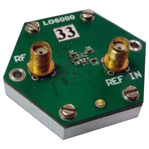
LO6000
REF1 10 MHz clock reference source used to provide reference clock inputs to local oscillators
- Number of Outputs: 4
- Output Frequency: 10 MHz
- Output Power: 11 dBm
- Frequency Stability: 2.5 ppm
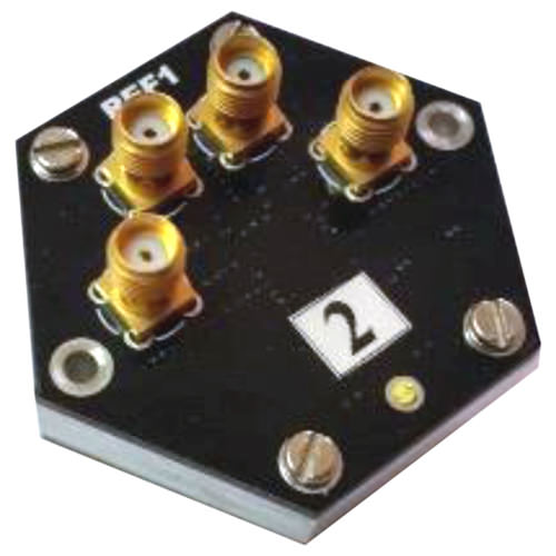
REF1
RFSW1 SPDT absorptive RF switch
- Frequency Range: 10 – 6000 MHz
- Insertion Loss: 1.5 dB (Typical)
- RFC Return Loss: -15 dB
- Active Port Return Loss: -15 dB
- Terminated Port Return Loss: -15 dB
- RF Input Power Handling (Active): 36 dBm
- RF Input Power Handling (Terminated): 26 dBm
- Input IP2 @ 2 GHz: 120 dBm
- Input IP3 @ 2 GHz: 65 dBm
- Max. RF input power:40 dBm
- Max. DC Voltage at input or output: 50 Vdc
- Isolation @ 2GHz : 50dB

RFSW1
RFSW2 SPDT absorptive RF switch
- Frequency Range: 30 – 5000 MHz
- Insertion Loss: 1.5 dB (Typical)
- RFC Return Loss: -20 dB
- Active Port Return Loss: -15 dB
- Terminated Port Return Loss: -17 dB
- RF Input Power Handling (Active): 33 dBm
- RF Input Power Handling (Terminated): 24 dBm
- Input IP2 @ 2 GHz: 97 dBm
- Input IP3 @ 2 GHz: 58 dBm
- Max. RF input power:35 dBm
- Max. DC Voltage at input or output: 50 Vdc
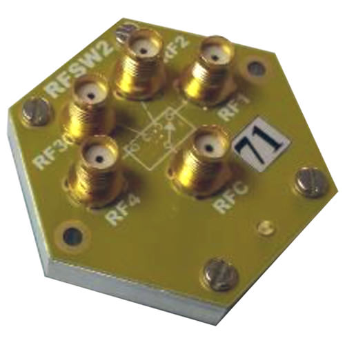
RFSW2
VAT6000 Wideband variable attenuator
- Frequency Range: 10 – 6000 MHz
- Insertion Loss: 2.5dB (ty)
- Attenuation Setting: -31.75 dB (min)
- Attenuation Resolution: 0.25dB (ty)
- Return Loss: -15dB (ty)
- RF Input Power :23dBm (max)
- Input IP3: 55dBm
- Max DC Voltage at input or output: 25 Volt
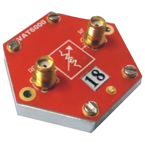
VAT6000
PWR1 Power Supply module providing DC supply to all other Beewave modules through the backplane
- Input Voltage: 12 Vdc (typical)
- Output Voltage: 3.3 Vdc and 5 Vdc
- Maximum output power: 30 Watt
- Efficiency: up to 89%
- Universal Input Range: 90-305VAC
- Input voltage reverse Protection
- Output Short Circuit and overload Protection
- 4 Additional Outputs (5V and 3.3V)
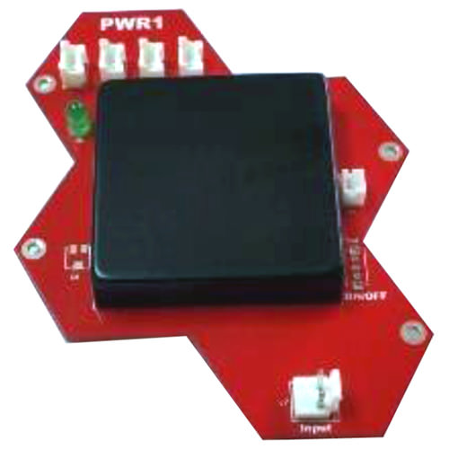
PWR1
30 otros productos en la misma categoría:
-
Scientech24...
-
Scientech24...
-
Scientech24...
-
Scientech23...
-
ScientechIT...
-
Scientech24...
-
Scientech24...
-
Scientech24...
-
Scientech24...
-
Scientech24...
-
Scientech24...
-
Scientech23...
-
Scientech23...
-
Scientech23...
-
Scientech23...
-
Scientech23...
-
Scientech23...
-
Scientech23...
-
Scientech23...
-
Scientech23...
-
Scientech24...
-
Scientech24...
-
Scientech24...
-
Scientech24...
-
Scientech24...
-
Scientech24...
-
Scientech24...
-
Scientech24...
-
Scientech24...
-
Nvis 6000...
550,00 €